TPM Range

TPM Range
The TPM range are in the form of a Synthetic Resin Bonded Paper tube hermetically sealed at both ends with resin . Axial terminations are via M5 x 12mm studs or tinned copper wire.
Specifications
They are impregnated and filled with a mineral oil. The container is a Synthetic Resin Bonded Paper tube sealed at both ends with resin assuring hermetic sealing. The capacitors are terminated with M5 x 12mm studs or tinned copper wire.
NOTE: The impregnant used is a non toxic highly purified and inhibited mineral oil.
Capacitance Range: 0.0005µF – 2µF. The tolerance is +/-10%. Other tolerances are available on request. Nominal values measured at 1kHz.
Temperature Range: -55ºC to 85ºC. The nominal voltage rating is applicable from -55ºC to 85ºC.
Temperature Coefficient: Capacitance will increase by 2% per 100ºC temperature rise.
Voltage Range: 1kV – 100kVDC.
Note: The impregnant used is a non-toxic highly purified and inhibited mineral oil.
APPLICATIONS:The TPM range of capacitors are specifically designed for high voltage filters and can be successfully used in the following applications. High Voltage Smoothing; Induction Heating; RF Transmitter Power Supplies; X-Ray Power Supplies.
Capacitance Range: 0.001µF – 2µF. The tolerance is +/-10%. Other tolerances are available on request. Nominal values measured at 1kHz.
Temperature Range: -40°C to 85°C. Derating is required for higher operating temperatures.
Temperature Coefficient: Capacitance will increase by 2% per 100°C temperature rise.
Voltage Range: 1kV – 100kVDC
RIPPLE:
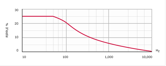
The sum of the peak ripple voltage and the DC voltage should not exceed the rated voltage. Refer to graph fig 1 for permissible peak-to-peak ripple voltage as a percentage of rated voltage for various frequencies.
| Test Voltage: V Test | ||
| For DC rating <20kV: | V Test = 2.0 x Rated Voltage for 1 minute. | |
| For DC rating ≥20kV: | V Test = 1.5 x Rated Voltage for 1 minute. | |
| Case to terminal Test voltage = V Test + 1kV |
Power Factor
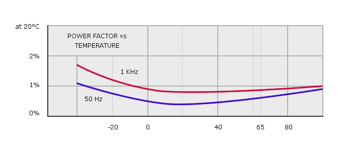
Power Factor: Variable; function of temperature and frequency. See fig 2. Nominal value < 0.5% at 20ºC.
Dieletric Resistance

Dieletric Resistance: (Parallel resistance) Indicated by the graph of insulance (Mohms x µF) vs Temperature (fig 3). The insulance(Mohms x µF) is nominally 10000s at +20ºC. (Measurements taken after 1 minute with an applied voltage of 500V).
Life expectancy

Life expectancy: TPM type capacitors are designed for a life expectancy of 50000 hours at 65ºC. To achieve the same life expectancy at 85ºC derate to 60% of rated voltage.

Dimensions

SELECT WORKING VOLTAGE:
| Voltage | Part No. | CAP | L mm | D mm |
| (VDC Wkg) | (uF) | |||
| 1000 | TPM10-103 | 0.01 | 42 | 17 |
| TPM10-503 | 0.05 | 48 | 20 | |
| TPM10-254 | 0.25 | 60 | 22 | |
| TPM10-504 | 0.5 | 70 | 30 | |
| TPM10-205 | 2 | 110 | 35 | |
| 2000 | TPM20-103 | 0.01 | 48 | 17 |
| TPM20-503 | 0.05 | 60 | 17 | |
| TPM20-104 | 0.1 | 60 | 22 | |
| TPM20-254 | 0.25 | 60 | 30 | |
| TPM20-504 | 0.5 | 75 | 35 | |
| 4000 | TPM40-102 | 0.001* | 42 | 17 |
| TPM40-103 | 0.01 | 42 | 20 | |
| TPM40-503 | 0.05 | 60 | 22 | |
| TPM40-104 | 0.1 | 60 | 30 | |
| TPM40-504 | 0.5 | 95 | 42 | |
| 6000 | TPM60-102 | 0.001* | 55 | 17 |
| TPM60-502 | 0.005* | 65 | 17 | |
| TPM60-203 | 0.02 | 80 | 20 | |
| TPM60-104 | 0.1 | 100 | 35 | |
| TPM60-254 | 0.25 | 135 | 42 | |
| 10000 | TPM100-102 | 0.001* | 65 | 17 |
| TPM100-103 | 0.01 | 80 | 22 | |
| TPM100-503 | 0.05 | 105 | 35 | |
| TPM100-104 | 0.1 | 170 | 35 | |
| TPM100-254 | 0.25 | 205 | 42 | |
| 15000 | TPM150-102 | 0.001* | 95 | 17 |
| TPM150-502 | 0.005* | 110 | 20 | |
| TPM150-103 | 0.01 | 110 | 30 | |
| TPM150-503 | 0.05 | 150 | 42 | |
| TPM150-104 | 0.1 | 245 | 42 | |
| 25000 | TPM250-501 | 0.0005* | 145 | 17 |
| TPM250-102 | 0.001 | 145 | 20 | |
| TPM250-502 | 0.005 | 175 | 30 | |
| TPM250-103 | 0.01 | 175 | 35 | |
| TPM250-503 | 0.05 | 300 | 42 | |
| 40000 | TPM400-102 | 0.001* | 210 | 20 |
| TPM400-202 | 0.002 | 275 | 20 | |
| TPM400-103 | 0.01 | 275 | 42 | |
| 1500 | TPM15-103 | 0.01* | 42 | 17 |
| TPM15-254 | 0.25 | 60 | 30 | |
| TPM15-504 | 0.5 | 110 | 30 | |
| TPM15-105 | 1 | 110 | 35 | |
| TPM15-205 | 2 | 110 | 42 | |
| 3000 | TPM30-502 | 0.005* | 42 | 17 |
| TPM30-203 | 0.02 | 48 | 20 | |
| TPM30-104 | 0.1 | 55 | 30 | |
| TPM30-504 | 0.5 | 75 | 42 | |
| TPM30-105 | 1 | 110 | 42 | |
| 5000 | TPM50-102 | 0.001* | 42 | 17 |
| TPM50-502 | 0.005* | 42 | 20 | |
| TPM50-103 | 0.01 | 48 | 20 | |
| TPM50-503 | 0.05 | 60 | 25 | |
| TPM50-254 | 0.25 | 95 | 35 | |
| 8000 | TPM80-502 | 0.005* | 65 | 20 |
| TPM80-103 | 0.01 | 80 | 20 | |
| TPM80-503 | 0.05 | 105 | 35 | |
| TPM80-104 | 0.1 | 105 | 42 | |
| TPM80-254 | 0.25 | 170 | 42 | |
| 12000 | TPM120-202 | 0.002* | 95 | 20 |
| TPM120-103 | 0.01 | 115 | 30 | |
| TPM120-203 | 0.02 | 115 | 35 | |
| TPM120-503 | 0.05 | 180 | 35 | |
| TPM120-104 | 0.1 | 180 | 42 | |
| 20000 | TPM200-102 | 0.001* | 115 | 22 |
| TPM200-103 | 0.01 | 145 | 30 | |
| TPM200-203 | 0.02 | 195 | 30 | |
| TPM200-503 | 0.05 | 245 | 42 | |
| TPM200-104 | 0.1 | 320 | 42 | |
| 30000 | TPM300-501 | 0.0005* | 170 | 17 |
| TPM300-202 | 0.002 | 170 | 25 | |
| TPM300-103 | 0.01 | 205 | 35 | |
| TPM300-203 | 0.02 | 280 | 35 | |
| TPM300-303 | 0.03 | 280 | 42 | |
| 50000 | TPM500-501 | 0.0005* | 275 | 22 |
| TPM500-202 | 0.002 | 340 | 22 | |
| TPM500-103 | 0.01 | 340 | 42 | |
NOTES:
DIMENSIONS IN MILLIMETRES +/- 1mm
Max. Torque on terminals = 2Nm