PMW Range

PMW Range
The PMW range are in the form of a welded heavy gauge mild steel can that is hermetically sealed. External connections are via ceramic bushings. The range may be supplied with fixing brackets, handles or lugs for lifting.
Specifications
They are impregnated and filled with a mineral oil. The container is manufactured from heavy gauge, cold rolled steel that is welded and hermetically sealed. The internal construction is designed to prevent movement when subjected to vibration or mechanical shock. The capacitors’ containers are primed and glossed. The capacitors may be supplied with fixing brackets, handles or lugs for lifting. Larger capacitors are mounted on wheels.
NOTE: The impregnant used is a non toxic highly refined, purified and inhibited mineral oil.
APPLICATIONS: The PMW range of capacitors are specially designed for DC filtering and bypass applications such as high voltage power supplies for lasers, radar and x-ray, RF transmitters, traction equipment and generators where reliability and long life are prime considerations.
Capacitance Range: 0.01µF-100µF. The tolerance is +/-10%. Other tolerances are available on request. Nominal values measured at 1kHz.
Temperature Range: -55°C to 85°C. The nominal voltage rating is applicable from -55°C to 85°C. Derating is required for higher operating temperatures.
Temperature Coefficient: Capacitance will increase by 2% per 100ºC temperature change.
Voltage Range: 1KVDC - 80kVDC
RIPPLE:
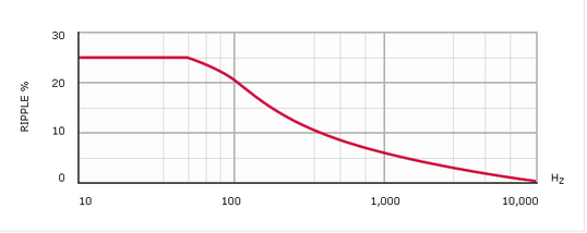
Ripple: The sum of the peak ripple voltage and the DC voltage should not exceed the rated voltage. The graph above shows permissible peak-to-peak ripple voltage as a percentage of rated voltage for various frequencies.
| Test Voltage: V Test | (Terminal to (Terminal) |
| For DCrating <20kV | Vtest=2.0 x Rated Voltage for 1 miute |
| For DC rating >20kV | Vtest=1.5x Rated Voltage for 1 minute |
| Case to terminal Test voltage | VTest+1kV (Note where necessary terminals are joined together during testing) |
| Test Voltage: V Test | ||
| For DC rating <20kV: | V Test = 2.0 x Rated Voltage for 1 minute. | |
| For DC rating ≥20kV: | V Test = 1.5 x Rated Voltage for 1 minute. | |
| Case to terminal Test voltage = V Test + 1kV |
Power Factor

Power Factor: Variable; function of temperature and frequency. See fig 2. Nominal value < 0.5% at 20ºC.
Dieletric Resistance

Dieletric Resistance: (Parallel resistance) Indicated by the graph of insulance (Mohms x µF) vs Temperature (fig 3). The insulance(Mohms x µF) is nominally 10000s at +20ºC. (Measurements taken after 1 minute with an applied voltage of 500V).
Life expectancy

Life expectancy: PMW type capacitors are designed for a life expectancy of 50000 hours at 65ºC. To achieve the same life expectancy at 85ºC derate to 60% of rated voltage.
Flashover
V Rated < 5kV, the terminals will withstand 125% of rated voltage without flashover @ 85mm Hg (equivalent to 50000 ft altitude).
V Rated > 5kV, the terminals will withstand 125% of rated voltage without flashover @ 500mm Hg (equivalent to 10000 ft altitude).
Dimensions

SELECT WORKING VOLTAGE:
| Kilovolts | Capacitance | A | B | C |
| DC | µF | |||
| 6 | 24 | 345 | 160 | 130 |
| 6 | 40 | 450 | 250 | 145 |
| 7.5 | 35 | 260 | 250 | 170 |
| 8 | 37 | 530 | 290 | 150 |
| 8 | 9 | 200 | 305 | 120 |
| 10 | 32 | 380 | 325 | 205 |
| 10 | 5 | 200 | 160 | 140 |
| 10 | 8 | 260 | 250 | 105 |
| 12 | 4 | 270 | 215 | 180 |
| 15 | 7 | 380 | 290 | 125 |
| 15 | 12 | 710 | 355 | 130 |
| 15 | 35 | 660 | 455 | 230 |
| 18 | 4 | 380 | 330 | 105 |
| 18 | 7 | 380 | 325 | 165 |
| 20 | 4 | 380 | 340 | 120 |
| 20 | 7 | 710 | 355 | 130 |
| 20 | 10 | 695 | 470 | 100 |
| 20 | 20 | 695 | 470 | 180 |
| 25 | 2 | 380 | 330 | 105 |
| 25 | 4 | 540 | 305 | 125 |
| 25 | 5 | 530 | 350 | 140 |
| 25 | 12 | 720 | 570 | 200 |
| 30 | 1 | 260 | 255 | 160 |
| 30 | 2 | 370 | 330 | 130 |
| 30 | 4 | 540 | 385 | 135 |
| 40 | 4 | 400 | 600 | 235 |
| 60 | 2 | 570 | 415 | 270 |
| 80 | 0.1 | 235 | 310 | 130 |