TLC Range

TLC Range
The TLC range of capacitors are similar in design to the TPM range but are housed in a more robust container with M6 x 15 axial stud terminals as standard.
Specifications
They utilise a mixed dielectric material that consists of polyester or polypropylene film and capacitor paper and are impregnated and filled with a mineral oil. The container is a Synthetic Resin Bonded Paper (SRBP) tube sealed at both ends with resin assuring a hermetic seal. The capacitors may be used in air, oil or SF6. They are terminated with M6 studs x 15mm long. (M10 x 20mm studs can also be supplied on request).
Note: The impregnant used is a non-toxic highly purified and mineral oil.
APPLICATIONS:The TLC range of capacitors are specifically designed for high voltage filters and can be successfully used in the following applications. High Voltage Smoothing; Induction Heating; RF Transmitter Power Supplies; X-Ray Power Supplies.
Capacitance Range: 0.001µF – 2µF. The tolerance is +/-10%. Other tolerances are available on request. Nominal values measured at 1kHz.
Temperature Range: -40°C to 85°C. Derating is required for higher operating temperatures.
Temperature Coefficient: Capacitance will increase by 2% per 100°C temperature rise.
Voltage Range: 1kV – 100kVDC
RIPPLE:
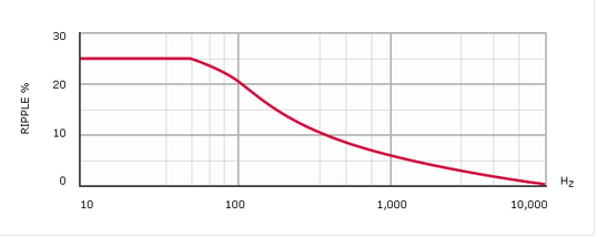
Ripple: The sum of the peak ripple voltage and the DC voltage should not exceed the rated voltage. The graph above shows permissible peak-to-peak ripple voltage as a percentage of rated voltage for various frequencies.
| Test Voltage: V Test | ||
| For DC rating <20kV: | V Test = 2.0 x Rated Voltage for 1 minute. | |
| For DC rating ≥20kV: | V Test = 1.5 x Rated Voltage for 1 minute. | |
| Case to terminal Test voltage = V Test + 1kV |
Power Factor

Power Factor: Variable; function of temperature and frequency. See fig 2. Nominal value < 0.5% at 20ºC.
Dieletric Resistance

Dieletric Resistance: (Parallel resistance) Indicated by the graph of insulance (Mohms x µF) vs Temperature (fig 3). The insulance(Mohms x µF) is nominally 10000s at +20ºC. (Measurements taken after 1 minute with an applied voltage of 500V).
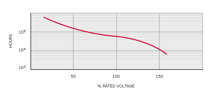
Life expectancy

Life expectancy: TLC type capacitors are designed for a life expectancy of 50000 hours at 65ºC. To achieve the same life expectancy at 85ºC derate to 60% of rated voltage.
Weight
The approximate weight in grams of capacitors in the TLC range can be estimated by multiplying the volume of the capacitor container by 1.2 x 10⁻³
Dimensions

SELECT WORKING VOLTAGE:
| Part No. | Cap µF | KiloVolts | L | D |
| TLC100-104 | 0.1 | 10 | 115 | 65 |
| TLC100-254 | 0.25 | 10 | 140 | 75 |
| TLC100-504 | 0.5 | 10 | 205 | 95 |
| TLC200-503 | 0.05 | 20 | 180 | 65 |
| TLC200-104 | 0.1 | 20 | 230 | 65 |
| TLC200-254 | 0.25 | 20 | 280 | 75 |
| TLC200-504 | 0.5 | 20 | 360 | 95 |
| TLC300-253 | 0.025 | 30 | 245 | 65 |
| TLC300-503 | 0.05 | 30 | 320 | 65 |
| TLC300-104 | 0.1 | 30 | 395 | 65 |
| TLC300-254 | 0.25 | 30 | 510 | 75 |
| TLC400-253 | 0.025 | 40 | 305 | 65 |
| TLC400-503X | 0.05 | 40 | 410 | 65 |
| TLC400-104 | 0.1 | 40 | 345 | 95 |
| TLC400-124 | 0.12 | 40 | 440 | 95 |
| TLC500-103 | 0.01 | 50 | 270 | 65 |
| TLC500-253 | 0.025 | 50 | 335 | 65 |
| TLC500-503 | 0.05 | 50 | 430 | 75 |
| TLC500-104 | 0.1 | 50 | 430 | 95 |
| TLC600-502 | 0.005 | 60 | 310 | 65 |
| TLC600-103 | 0.01 | 60 | 310 | 75 |
| TLC600-253 | 0.025 | 60 | 390 | 75 |
| TLC600-503 | 0.05 | 60 | 500 | 75 |
| TLC600-104 | 0.1 | 60 | 615 | 95 |
| TLC800-502 | 0.005 | 80 | 400 | 65 |
| TLC800-103 | 0.01 | 80 | 400 | 75 |
| TLC800-253 | 0.025 | 80 | 500 | 95 |
| TLC800-503 | 0.05 | 80 | 650 | 95 |
| TLC1000-502 | 0.005 | 100 | 485 | 65 |
| TLC1000-103 | 0.01 | 100 | 485 | 75 |
| TLC1000-253 | 0.025 | 100 | 690 | 95 |
| TLC1000-502 | 0.005 | 120 | 425 | 75 |
NOTES:
DIMENSIONS IN MILLIMETRES +/- 1mm
Max. Torque on terminals = 2Nm